Phase synchronization of output signals across multiple Moku devices
Waveform Generator output phase sync

Written by Paul Cracknell
Updated at January 14th, 2026
-
Moku:Go
Moku:Go General Moku:Go Arbitrary Waveform Generator Moku:Go Data Logger Moku:Go Digital Filter Box Moku:Go FIR Filter Builder Moku:Go Frequency Response Analyzer Moku:Go Logic Analyzer & Pattern Generator Moku:Go Oscilloscope & Voltmeter Moku:Go PID Controller Moku:Go Spectrum Analyzer Moku:Go Waveform Generator Moku:Go Power Supplies Moku:Go Lock-in Amplifier Moku:Go Time & Frequency Analyzer Moku:Go Laser Lock Box Moku:Go Phasemeter
-
Moku:Lab
Moku:Lab General Moku:Lab Arbitrary Waveform Generator Moku:Lab Data Logger Moku:Lab Digital Filter Box Moku:Lab FIR Filter Builder Moku:Lab Frequency Response Analyzer Moku:Lab Laser Lock Box Moku:Lab Lock-in Amplifier Moku:Lab Oscilloscope Moku:Lab Phasemeter Moku:Lab PID Controller Moku:Lab Spectrum Analyzer Moku:Lab Time & Frequency Analyzer Moku:Lab Waveform Generator Moku:Lab Logic Analyzer/Pattern Generator
-
Moku:Pro
Moku:Pro General Moku:Pro Arbitrary Waveform Generator Moku:Pro Data Logger Moku:Pro Frequency Response Analyzer Moku:Pro Oscilloscope Moku:Pro PID Controller Moku:Pro Spectrum Analyzer Moku:Pro Waveform Generator Moku:Pro Lock-in Amplifier Moku:Pro Laser Lock Box Moku:Pro Digital Filter Box Moku:Pro FIR Filter Builder Moku:Pro Phasemeter Moku:Pro Multi-instrument Mode Moku:Pro Logic Analyzer/Pattern Generator Moku:Pro Time & Frequency Analyzer
- Python API
- MATLAB API
- Arbitrary Waveform Generator
- Data Logger
- Digital Filter Box
- FIR Filter Builder
- Frequency Response Analyzer
- Laser Lock Box
- Lock-in Amplifier
- Oscilloscope
- Phasemeter
- PID Controller
- Spectrum Analyzer
- Time & Frequency Analyzer
- Waveform Generator
- Logic Analyzer & Pattern Generator
- Multi Instrument Mode
- Moku Cloud Compile
- Moku general
- LabVIEW
- mokucli
If you would like to generate signals (with synchronized phase) in more than the number of output channels available on a Moku device, you can connect multiple Mokus to achieve this. This feature is only available on Moku:Delta, Moku:Pro, and Moku:Lab, as these hardware contain clock synchronization reference ports on the back of the devices. Moku:Go is the only current hardware without this feature.
The generated signal is synchronized by triggering the Waveform Generator with the same output signal from the Oscilloscope.
This is a step by step guide to show how to generate 4 sine wave signals of the same frequency with synchronized phase using two Moku:Labs. A third Moku:Lab is used as an Oscilloscope to measure the signal generated from the Waveform Generators. NOTE: This can also be configured on Moku:Pros and Moku:Deltas with the same process.
1. Clock synchronization
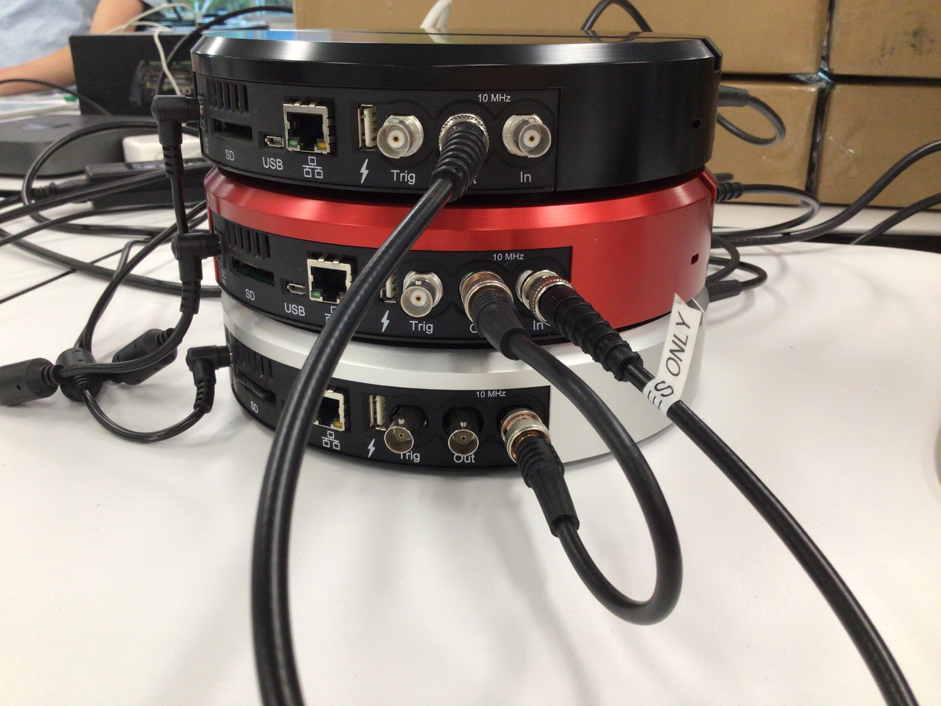
The 10 MHz clocks on all three Moku:Labs need to be synchronized. Using one of the Moku:Lab's Waveform Generator as the master (black unit on the top in this example), it outputs the 10 MHz reference signal to the second Moku:Lab (red unit), which then outputs to the third Moku:Lab (silver unit).
In the Moku app, the first Moku:Lab (black) should be selected. Open the hamburger menu in the top-left corner and hover over “External 10 MHz clock” and select “Always use internal”. This will switch to the Moku:Lab’s internal clock. If the option already shows “Internal 10 MHz clock”, no action is required. Repeat the steps above for the other two Moku:Labs, but ensure the setting is the opposite. These units should be configured to use an external clock, which will be provided by the first Moku:Lab.
2. Waveform Generator setup
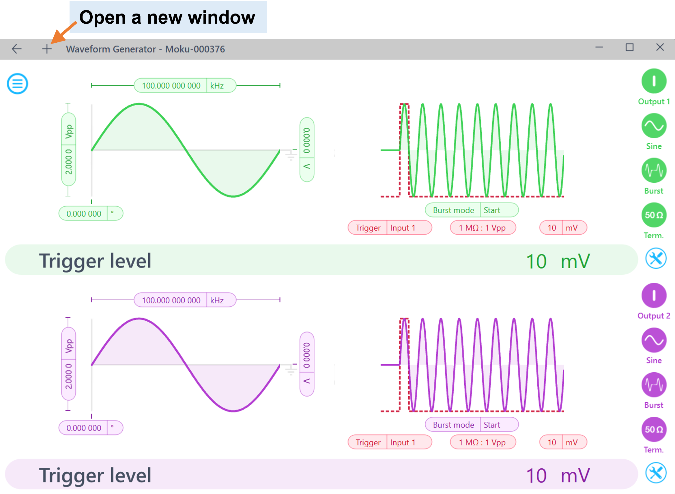
Starting from Moku version 3.2, users can control all of their Moku devices simultaneously, which enables the multi-window Waveform Generator control.
Software setup:
For Waveform Generator Moku:Labs 1 and 2:
- Define Waveform Generator Output signal properties, i.e. waveform, frequency, and amplitude.
- Set modulation to "Burst" mode, burst mode to "Start", modulation trigger to "Input 1" "10 mV".
- Enable the output on both channels and both Moku:Labs.
Hardware setup:
- Connect a signal splitter to Output 1 of the Oscilloscope Moku:Lab, connect the signal splitter to Input 1 of Waveform Generator Moku:Lab 1 and Input 1 of Waveform Generator Moku:Lab 2. (Note: we recommend using BNC cables with the same length for the trigger signal for both Moku:Labs, as cable latency may cause delayed triggering and phase difference). You can also use the trigger port on the back of any device (excluding Moku:Go) instead of an input port if all inputs are needed for other measurements.
- Connect Output 1 of Waveform Generator Moku:Lab 1 to Input 1 of the Oscilloscope Moku:Lab.
- Connect Output 1 of Waveform Generator Moku:Lab 2 to Input 2 of the Oscilloscope Moku:Lab
3. Oscilloscope setup
Set the Oscilloscope Output 1 to square wave with an amplitude of 2 Vpp and frequency of 1 kHz. This output signal will be the trigger for both Waveform Generators to start generating signal, hence the phase will be synchronized.
As you enable Output 1, you should be able to see the output signals from both Waveform Generator Moku:Labs and they should be synced in phase. You can switch around the four output channels and should be able to see all signals are phase synchronized.