What is the minimum step size of the frequency in sweep mode?
-
Moku:Go
Moku:Go General Moku:Go Arbitrary Waveform Generator Moku:Go Data Logger Moku:Go Digital Filter Box Moku:Go FIR Filter Builder Moku:Go Frequency Response Analyzer Moku:Go Logic Analyzer & Pattern Generator Moku:Go Oscilloscope & Voltmeter Moku:Go PID Controller Moku:Go Spectrum Analyzer Moku:Go Waveform Generator Moku:Go Power Supplies Moku:Go Lock-in Amplifier Moku:Go Time & Frequency Analyzer Moku:Go Laser Lock Box Moku:Go Phasemeter
-
Moku:Lab
Moku:Lab General Moku:Lab Arbitrary Waveform Generator Moku:Lab Data Logger Moku:Lab Digital Filter Box Moku:Lab FIR Filter Builder Moku:Lab Frequency Response Analyzer Moku:Lab Laser Lock Box Moku:Lab Lock-in Amplifier Moku:Lab Oscilloscope Moku:Lab Phasemeter Moku:Lab PID Controller Moku:Lab Spectrum Analyzer Moku:Lab Time & Frequency Analyzer Moku:Lab Waveform Generator Moku:Lab Logic Analyzer/Pattern Generator
-
Moku:Pro
Moku:Pro General Moku:Pro Arbitrary Waveform Generator Moku:Pro Data Logger Moku:Pro Frequency Response Analyzer Moku:Pro Oscilloscope Moku:Pro PID Controller Moku:Pro Spectrum Analyzer Moku:Pro Waveform Generator Moku:Pro Lock-in Amplifier Moku:Pro Laser Lock Box Moku:Pro Digital Filter Box Moku:Pro FIR Filter Builder Moku:Pro Phasemeter Moku:Pro Multi-instrument Mode Moku:Pro Logic Analyzer/Pattern Generator Moku:Pro Time & Frequency Analyzer
- Python API
- MATLAB API
- Arbitrary Waveform Generator
- Data Logger
- Digital Filter Box
- FIR Filter Builder
- Frequency Response Analyzer
- Laser Lock Box
- Lock-in Amplifier
- Oscilloscope
- Phasemeter
- PID Controller
- Spectrum Analyzer
- Time & Frequency Analyzer
- Waveform Generator
- Logic Analyzer & Pattern Generator
- Multi Instrument Mode
- Moku Cloud Compile
- Moku general
- LabVIEW
- mokucli
What is frequency sweep mode ?
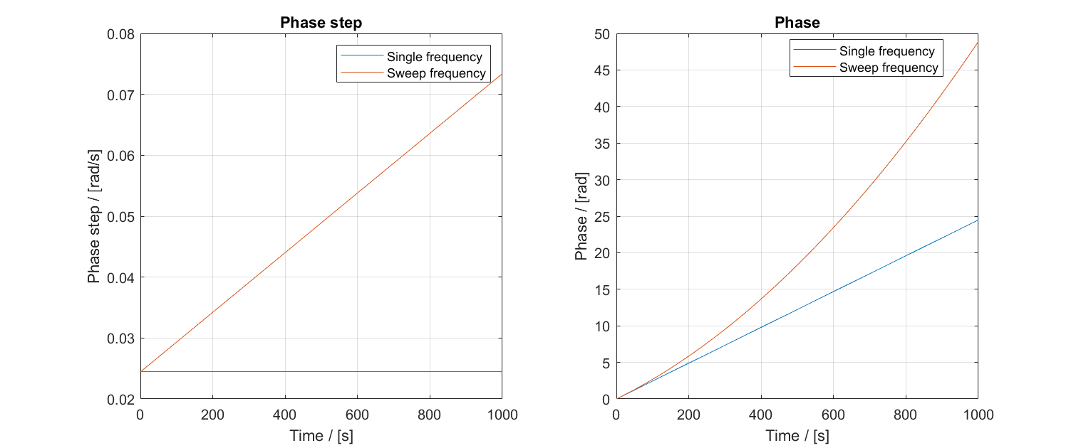
The Waveform Generator incorporates various modulation techniques, including Amplitude Modulation (AM), Phase Modulation (PM), and Sweep frequency Modulation. In the plot below, both the phase step (frequency) and the ramped phase are depicted to illustrate the difference in two modes. In a single frequency mode, the phase step remains constant, and the phase counter increments by the size of the phase step, resembling a first-order function. On the other hand, sweep frequency modulation has a gradual increase in the phase step from the initial value to the final frequency over the sweep duration. Throughout this duration, both the phase step and the phase counter are incremented, resulting in a second-order function.

The following figure plots the sine wave corresponding to the generated phase. It is obvious that the frequency of the orange line (sweep mode) gradually increases over time.

What is the minimum sweep frequency resolution?
In an ideal scenario, the sweep frequency resolution depends on the minimum resolution of the phase step. However, this principle doesn't hold when the precision of the internal phase counter doesn't align with that of the waveform generator phase counter.
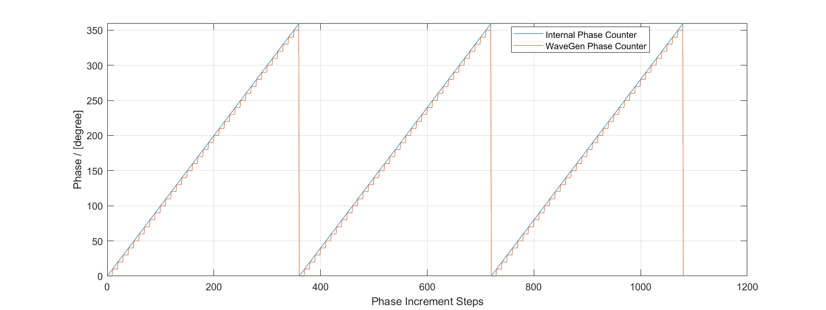
The internal phase counter in Moku:Pro boasts a higher bit width than the waveform generator phase counter, resulting in a mismatch between the minimum frequency step of a single-tone continuous waveform and the minimum observable frequency step in frequency sweeping mode. This discrepancy is attributed to truncated bits, which may introduce quantization errors in the phase, impacting the generated output waveform.


While the internal phase counter achieves high precision in the magnitude of better than nanohertz (nHz), it may face challenges when incrementing the lower precision phase counter within very short intervals. Consequently, the output waveform may not effectively capture the phase changes induced by nHz frequency steps in durations less than 1 second. For short sweep durations, the internal phase counter accurately increments, but a small phase step may not produce a noticeable change in the least significant bit (LSB) of the waveform generator phase counter.
In the worst-case scenario, with a 1-millisecond (ms) sweep duration in single sweep mode, the minimum frequency step size required to introduce a phase change in the output waveform is better than 4 microhertz (uHz). However, in most scenarios, particularly those with a sweep duration exceeding 1 second, the minimum frequency step size is expected to be better than 1 nHz.
Why do we have different phase counter resolutions?
To ensure a reliable minimum frequency resolution, a high sampling rate device requires a substantial bit width for phase counting. For instance, a 1 MSa/s DAC necessitates at least log₂(1,000,000) = 20 bits to generate a 1 Hz signal, while a 300 MSa/s device demands 29 bits for the same task. Moku:Pro boasts a significantly large bit width, exceeding 60 bits, enabling accurate frequency resolution down to less than 1 uHz.
The decision to truncate the internal phase counter to match the WaveGen phase counter arises from the resolution limit of the digital-to-analog converter (DAC) in Moku, which has a 16-bit resolution. A 16-bit DAC is only capable of generating 2^16 distinct voltage amplitudes. Consequently, adding extra bits to the WaveGen phase counter wouldn't contribute to further enhancing the resolution of the output waveform. Therefore, constraining the bit width of the WaveGen Phase Counter proves to be a more efficient approach to waveform generation.