How do I adjust the output voltage range limits on Moku:Pro?

Written by Laura Becerra
Updated at April 3rd, 2025
-
Moku:Go
Moku:Go General Moku:Go Arbitrary Waveform Generator Moku:Go Data Logger Moku:Go Digital Filter Box Moku:Go FIR Filter Builder Moku:Go Frequency Response Analyzer Moku:Go Logic Analyzer & Pattern Generator Moku:Go Oscilloscope & Voltmeter Moku:Go PID Controller Moku:Go Spectrum Analyzer Moku:Go Waveform Generator Moku:Go Power Supplies Moku:Go Lock-in Amplifier Moku:Go Time & Frequency Analyzer Moku:Go Laser Lock Box Moku:Go Phasemeter
-
Moku:Lab
Moku:Lab General Moku:Lab Arbitrary Waveform Generator Moku:Lab Data Logger Moku:Lab Digital Filter Box Moku:Lab FIR Filter Builder Moku:Lab Frequency Response Analyzer Moku:Lab Laser Lock Box Moku:Lab Lock-in Amplifier Moku:Lab Oscilloscope Moku:Lab Phasemeter Moku:Lab PID Controller Moku:Lab Spectrum Analyzer Moku:Lab Time & Frequency Analyzer Moku:Lab Waveform Generator Moku:Lab Logic Analyzer/Pattern Generator
-
Moku:Pro
Moku:Pro General Moku:Pro Arbitrary Waveform Generator Moku:Pro Data Logger Moku:Pro Frequency Response Analyzer Moku:Pro Oscilloscope Moku:Pro PID Controller Moku:Pro Spectrum Analyzer Moku:Pro Waveform Generator Moku:Pro Lock-in Amplifier Moku:Pro Laser Lock Box Moku:Pro Digital Filter Box Moku:Pro FIR Filter Builder Moku:Pro Phasemeter Moku:Pro Multi-instrument Mode Moku:Pro Logic Analyzer/Pattern Generator Moku:Pro Time & Frequency Analyzer
- Python API
- MATLAB API
- Arbitrary Waveform Generator
- Data Logger
- Digital Filter Box
- FIR Filter Builder
- Frequency Response Analyzer
- Laser Lock Box
- Lock-in Amplifier
- Oscilloscope
- Phasemeter
- PID Controller
- Spectrum Analyzer
- Time & Frequency Analyzer
- Waveform Generator
- Logic Analyzer & Pattern Generator
- Multi Instrument Mode
- Moku Cloud Compile
- Moku general
- LabVIEW
- mokucli
Moku:Pro has two options for output voltage range into 50 Ohms: +/- 1V (2 Vpp) and +/- 5V (10 Vpp).
To adjust the output voltage range on the Lock In Amplifier, FIR Filter Builder, PID Controller, Digital Filter Box, and Laser Lock Box, the output gain on the right hand side should be selected and changed to 0 dB for +/- 1V and +14 dB for +/- 5V as shown in the following image.

To adjust the output voltage range in Multi-Instrument Mode, the output gain is located at the bottom of the window as shown in the following image.

Some instruments modify the output voltage range by directly setting the voltage limits in the settings panel on the right hand side of the screen. The following image shows where the output amplitude settings can be modified in the Spectrum Analyzer (top), Time & Frequency Analyzer (middle), and Phasemeter (bottom).

The output voltage ranges in the Waveform Generator and Arbitrary Waveform Generator are directly set using the amplitude settings on the left hand side. Output range limits of the Arbitrary Waveform Generator are restricted to +/- 1V if the sample rate is above 312.5 MSa/s.
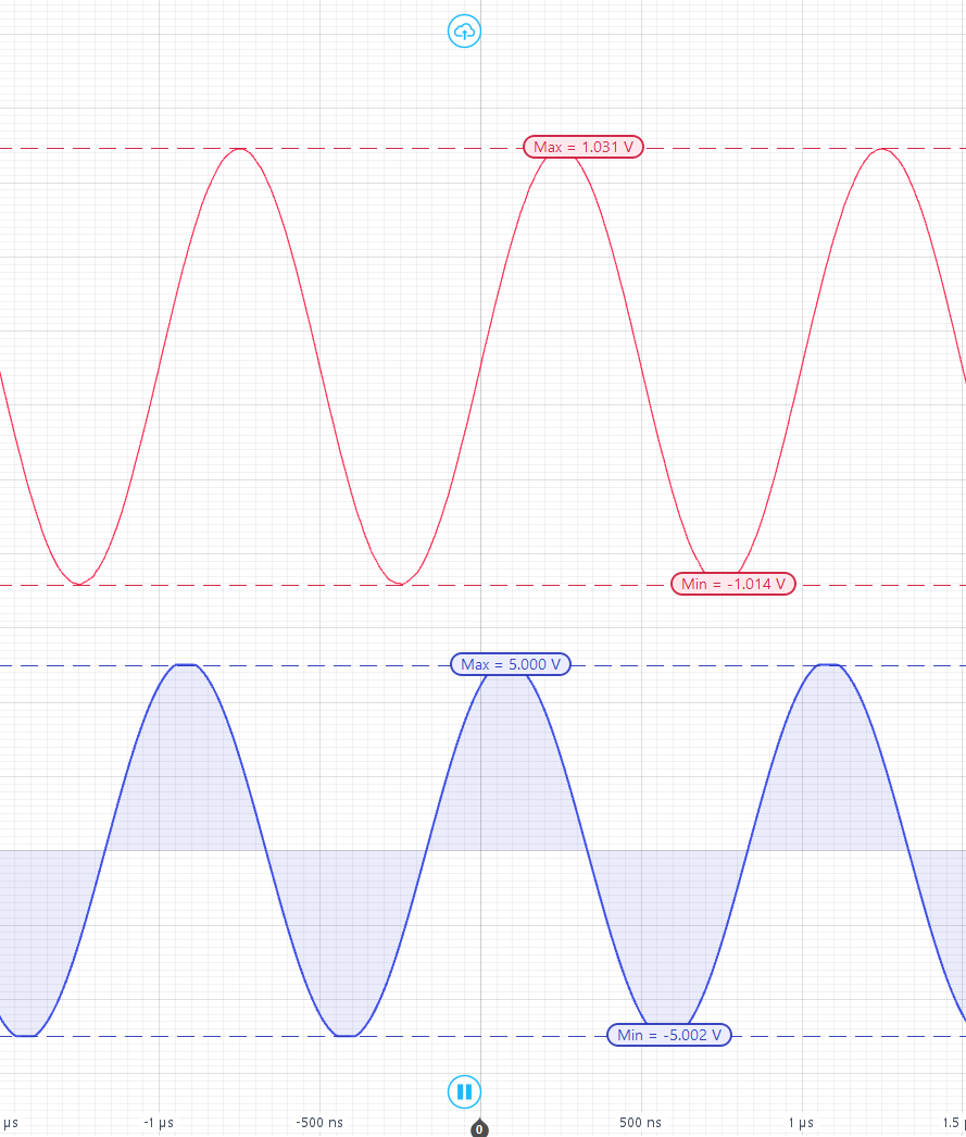
In MiM the signal coming out of the Waveform Generator or Arbitrary Waveform Generator does not know whether it is being routed to another instrument slot or to the Moku:Pro output.
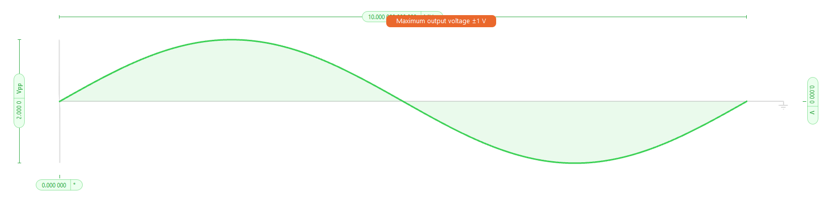
The maximum amplitude between instrument slots is 2 Vpp, so in the WG/AWG amplitude settings it is limited to 2 Vpp. However, when the signal is routed to the Moku:Pro output, the selected gain is applied to the output signal.
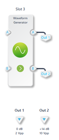
This means that if you set a sinewave to 2 Vpp in the WG/AWG and route it to a Moku:Pro output with +14 dB gain selected, then the signal generated will be a 10 Vpp sine wave. If a 0 dB gain is applied then a 2 Vpp sine wave will be output.